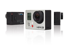
Socionext GoPro GP2 Research on the GoPro HERO11 Black Mini
Posted by Mark Kirschenbaum on
Although my research is not complete, I've ascertained enough details about the Socionext/GoPro GP2 that it's time to release my notes. Below is my working journal as I study an unknown, undocumented processor. There are definitely some big changes from the GoPro GP1 processor, but the codebase remains roughly the same.
I suggest reading the GoPro GP1 Research before continuing on as this blog builds upon that device. Also, be sure to read the teardowns of the GoPro HERO11/Mini and the GoPro HERO10.
Specifications
- Codename: Socionext Milbeaut m20v
- Quad aarch64 Cortex-A53 up to 800Mhz, 1Ghz overdrive
- Micron 4GB LPDDR Package on Package
- Linux on one core, RTOS t-Kernel on the other three
- Integrated CEVA-XM6 DSP Core
- L1 I-Cache: 64 KBytes
- L1 D-Cache: 32 KBytes
- L2 D-Cache: 1024 KBytes
- TSMC 12FFC process FinFET*
Scoring Serial
One of my first steps, after getting the watertight-sealed GoPro split, was finding the serial Tx and Rx pins. The GoPro has two operating systems running concurrently, an T-Kernel RTOS and Linux. Each of these have dedicated uarts for console access. My general methodology is to reset the device under test (DUT) and probe test pads with my oscilloscope. I'm looking for the bootup console splash sequence.
I've found these DSD Tech 1V8 FTDI adapters from Amazon work well on windows and linux boxes, additionally, they're super inexpensive. Additionally, Joe Fitz's Tigard is an awesome multitool for those using Linux and iOS operating systems.
Resetting the GoPro HERO11 Mini inside the case while probing became difficult without easy access to the mode button. Therefore, I located the mode button test pad to power up the board before each test pad probe hit. In the end, I found it best to tear apart the whole GoPro and have it connected on my desk.
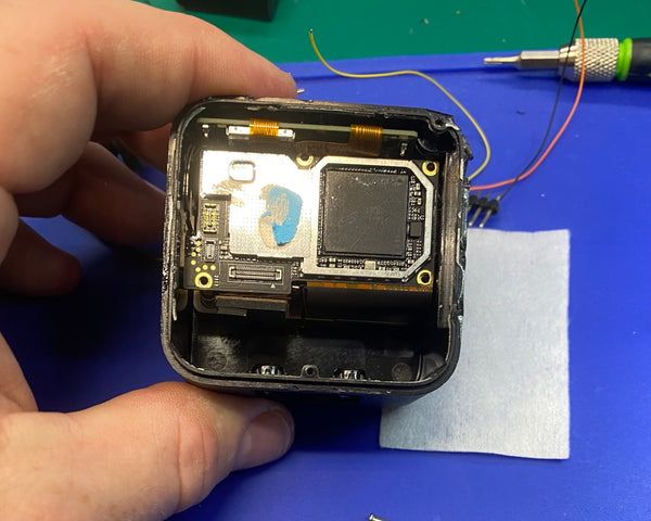
Power
With it torn apart, I added a VUSB+ input vs. the battery and continued probing for the UARTs. Here are the located power sources.
VBATT ~4.4v

VUSB (5volt)
![]()
...and Serial
The 1.8volt Linux console out (Tx) was easily found and the assumption was made Linux In (Rx) laid nearby. This pin was located and noted that it was tied to a 10K pullup. From that we could locate the RTOS Rx and figured the alignment was the same as linux. GoPro turns off the console for the RTOS but it will echo your commands when found. Issuing:
t dbg on
will turn on the debug messages.

Teardown Timelapse
This is my process opening the GoPro HERO11 Mini and finding the serial pins. Slow it down if you are interested in various parts.
GoPro HERO11 Mini for Drones, Naked, de-cased Version
Many people come to us for help getting their GoPro's working for drone and cinewhoop applications. Below are the test pads for the shutter and mode switches. Additionally, you will need to add VBUS+ at 5v and VBatt for the GoPro HERO11 Black Mini to operate without a battery. All the mounting holes are ground.
Excuse our additional wires as they are for the GP2 debugging.
NOTE: These shutter and mode test pads have a diode for protection. None-the-less, the input should be open drain. In other words from high-z to ground.

Standalone Power
USE CAUTION!
NOT RESPONSIBLE FOR BURNING OUT YOUR CAMERA.
NO REVERSE POLARITY PROTECTION!
There are a few ways to power on the GoPro HERO11 Mini without a battery pack. One of the ways is to directly connect VUSB to VBATT. Although VBATT max is around 4.4v the switcher seems to handle the over voltage just fine. If you're worried, just add a standard diode from VUSB to VBATT to drop the voltage.
Method 1:
Below is the modification I made. Notice how the red wire bridges the tall capacitor on VUSB and pin 5 of the switch for VBATT+. Please ignore my other wires used for testing. The small 0204 capacitor is not tied to the big 0603 cap, but it appears so in the image due to lack of depth.
Then use either VUSB or VBATT+ test pads to +5v to power.
METHOD 2:
Connect the VBATT+ pads and VUSB to your +5V power source. Their location is shown in the above Power section.
Again, be careful and protect against over voltages. In other words, use a regulated power source.
Max current consumption is over 1.2AMPS!
IMPORTANT! You will need your battery to update the GoPro in the future.
Use this at your own risk! Hypoxic and Trunk are not liable for damages this causes!!!!

PLEASE READ WARNINGS ABOVE! USE WITH CAUTION
JTAG-IN'
As I wanted complete control of the GP2, I decided to locate the JTAG pins. Using Joe Grand's JTAGULATOR and deducing I need six contiguous pins, I was able to quickly assign the functionality.
Then using Joe Fitz's Tigard, I begun creating an OpenOCD configuration file. The resulting file can be found here but it is very preliminary.
Please note, that the supervisor will reset the GP2 if the heartbeat is not given by the GP2 within a timeframe. To disable this watchdog, you must send the following to the RTOS via serial.
t frw mcu heartbeat 0
Development Connector Pinout
The below pin out numbering scheme is my own. Most likely their numbering scheme toggles between the two rows.
![]()
CAUTION: 1.8 volt serial and jtag signals required!
| Pin | Use | Pin | Use |
| 1 | Moorea SWD | 16 | 4 volt sense |
| 2 | Moorea SWD | 17 | x Not Inspected (float) |
| 3 | nMode Button No diode must be 1.8v |
18 | x Not Inspected |
| 4 | JTAG TCLK | 19 | nShutter Button No diode must be 1.8v |
| 5 | JTAG TDO | 20 | Linux serial Out |
| 6 | JTAG TDI | 21 | Linux serial In |
| 7 | JTAG TMS | 22 | RTOS serial Out |
| 8 | JTAG TRST | 23 | RTOS serial In |
| 9 | JTAG SRST | 24 | x Not Inspected |
| 10 | GND | 25 | GND |
| 11 | x Not Inspected | 26 | x Not Inspected |
| 12 | x Not Inspected | 27 | x Not Inspected |
| 13 | x Not Inspected | 28 | x Not Inspected |
| 14 | x Not Inspected | 29 | GND |
| 15 | 1V8 (target VDD) | 30 | x Not Inspected |
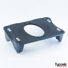
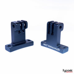
Since I plan on having this GoPro as my GP2 development hardware, I ended up building a platform for the debug pins. I've found this more reliable than constantly second guessing if a pin broke off or shorted the hardware.
Care must be taken as there is no heat sink and running at 100% CPU can put it into thermal shutdown quickly!

Security Enclave "Moorea"
Similar to all GoPro's since, and including, the GoPro HERO5, the GoPro HERO11 has an external supervisor microcontroller. Updated on the GoPro HERO11 & Mini, the supervisor now resides in a STMicro STM32G08 part. It is named Moorea.
Functionality:
- USB-C PD controller via FUSB302
- Multiplexor controller for the various accessories over USB-C (audio, Slimbus, i2c)
- ATSHA204 validator for genuine GoPro Accessories
- TI BQ battery authenticator and health interface
- Watchdog / heartbeat
- Unique identifier housing
- RTC and wakeup clock with backup battery
Updating
Updates of Moorea are signed and encrypted. Decryption key is not yet known but SCA on STMicro devices have worked in the past. A development kit is on order.
Firmware Updates
New to the GP2,are signed firmware updates. The bootstrap up to the Linux & RTOS operating systems are signed. Interesting to note is the bootstrap (EL3 supervisor code) uses a different key than the rest of the firmware.
This key, along with the signature type, is programmed in OTP e-fuses.
Below is what we know about the functionality, loading addresses, and signature of the various partitions.
|
|
Type | Function | Sign | Loading Address |
| bootrom | - | verifies and calls bootstrap |
rom | 08100000 |
| Boot | 0 |
EL3 Code |
Yes Key0 |
08200000 |
| - | eMMC Partition Tables [0x000:0x0800] Primary [0x800:0x1000] Secondary |
- | ||
| 0 | 0 | DDR Config[not in update] DDRCONFIG: 0x1000 ACSM:0x11000 DSP Code IMEM(u16): 0x12C00->5000 DMEM0:0x18C00->58000 DMEM1:0x20C00->5C000 |
No | 0x5000 |
| 2 | - | Calibration | - | - |
| 4 | 1 | RTOS | Yes Key1 |
40200000 |
| 5 | ||||
| 7 | 2 | Linux | Yes Key1 |
50080000 |
| 8 | 3 | RootFS | No | 45400000 |
| 9 | 2 | Device Tree (dtb) | Yes Key1 |
50000000 |
| 10 | - | Preferences | - | - |
| 12 | - | Vendor | - | - |
Mounts / Drives
As with the GP1, there are 4 FAT16 "drives" proceeding the standard eMMC tables. Two 512MB, two 1GB.
Signatures
GoPro Inc. uses NIST256p ECDSA to sign the various sections. The bootrom reads the loader's public key from an internal key-store. For the rest of the firmware partitions, the signature is hard coded.
The SHA256 hash and signature is validated before programming the various partitions. The bootstrap code is the only code whose signature is verified before running.
For completeness the public keys are provided below:
Public Key 0 - Bootstrap (e-Fuse):
0410acc22d955ee99c892ff2d8c425feba15535505c13a1ac41abe54e9e991f05ee2d3c49af00ca60cf511f831242d28b69a7b744531fa02538dd6ae2ef1f2deb6

Public Key 1 - User Space (Bootstrap):
0441a5d7de256fab0bee9989283fa7cdaacdbe748cf80014f473d5cb4c0851d89ed139dd43b3ba99144d16cb9716285620c0a61deef7a9afff2aaf124d21b158f5
BootROM
Unfortunately, the bootROM now requires a signed SD.DAT or USB supplied image to run EL3 security level code. Therefore, a third party recovery tool may not be possible if the camera is bricked.
Signature Header
In addition to the MILBEAUT header, signed sections also contain the following data. The public key is missing from key 1 sections.
Notice, just the signatures and hash in this table are big endian so native ARM loads need to byte swap the uint32.
Offsets given below are without the MILBEAUT partition header of 0x10 length.
[b'MILBEAUT'] [u16:type] [u16:partition] [u32:length in bytes]
| Offset | Byte len | Purpose |
| 0 | 4 | 'GPRO' Magic Key |
| 4 | 0x20 | ecdsa _r point |
| 0x24 | 0x20 | ecdsa_s point |
| 0x44 | 0x20 | sha256 hash |
| 0x64 | 0x40 | raw public key (no DER identifier) |
| 0xA4 | 0x20 | sha256 post vector |
| -- | -- | -- |
| 0xB4 | sha256 calculation start |
|
| 0xB4 | 4 | always '1' |
| 0xB8 | 4 | header len? |
| 0xBC | 4 |
data length |
| 0xC0 | 4 |
always '1' - |
| 0xC4 | 4 |
Signing type [ignored] |
| 0xC8 | 0x10 |
Possible iv or nonce |
| 0x200 | - |
Start of data |
SHA256
The SHA256 calculations starts at header offset 0xB4 and continues through the data. It then adds the "sha256 post vector" 0x10 bytes in an attempt to obfuscate the sha256 calculation.
Conclusion
More work is still to be done, but I'm happy with my understanding of this processor and it's security. All I ask is you please link this document if you use this information for your own endeavors. This is weeks of work I'm providing for free.
Research is ongoing. Please checkback soon!
Thank you
-Trunk
LEGAL: This product and/or service is not affiliated with, endorsed by, or in any way associated with GoPro Inc. or its products and services. GoPro, HERO, and their respective logos are trademarks or registered trademarks of GoPro, Inc. HEROBUS and BACPAC are trademarks of GoPro Inc.
* Process information from Tech Insights
https://www.techinsights.com/products/dfr-2202-803
Share this post
- Tags: gopro GP2, gopro hacker, teardown